From the three aspects of system networking scheme design, system installation design and system on-site commissioning, the design and application of power supply monitoring system for a certain store fire equipment are introduced.
Lin Weidong 1 Jiang Leijie 2 Yan Shanyong 2 Yan Lixia 2
(1.Fujian Provincial Architectural Design and Research Institute, Fuzhou 350001, China)
(2. Ankerui Electric Co., Ltd., Jiading, Shanghai 201801, China)
Abstract: This paper introduces the design and application of the power supply monitoring system of a fire service in a shopping mall from three aspects: system networking design, system installation design and system on-site debugging.
Key words: system networking design; system installation design; system on-site debugging; fire equipment power status monitor; sensor
0 Preface
The fire safety of a building depends largely on the quality of the fire fighting equipment, and the fire fighting equipment can work normally depending on the working state of the power supply. Fire-fighting equipment has been out of control due to the loss of control of power supply to fire-fighting equipment. The spread of fire has occurred frequently, especially in times when power supply is tight, equipment quality is poor, and safety awareness is weak. How to realize the real-time monitoring of the working state of the power supply of fire-fighting equipment from the technical defense means has been highly valued by the public security fire department. And in the implementation of GB 25506-2010 "General Technical Requirements for Fire Control Room", which was implemented on July 1, 2011, "The fire control room should be able to display the working status of the power supply and backup power of the fire-fighting equipment. Mandatory provisions for undervoltage alarm information [1]. GB 28184-2011 "Fire Equipment Power Monitoring System" was also promulgated on December 28, 2011, and implemented on August 1, 2012. This standard mandates the basic functions, test and inspection rules of fire equipment power monitoring system [2].
1 Project Overview
A shopping complex, with 7 floors above ground and 4 floors underground, with a total construction area of ​​over 110,000 m2, is a type of high-rise building. The main functions are monopoly, catering, cinema, garden, boutique and service package. The underground 2~4 floors are parking garages. The underground 1st floor and the 1st to 7th floors are dedicated to dining, cinema, cinema, boutiques and service packages. In the area, the roof is partially used for equipment.
According to the requirements of intelligent management, it is necessary to carry out continuous monitoring, centralized control and unified scheduling of the whole process of the working state of the fire-fighting equipment power supply of the entire complex building.
2 Fire equipment power monitoring system introduction
The AFPM fire equipment power monitoring system can monitor the working status of the fire equipment power supply in real time. By detecting the voltage, current, switch status and other related equipment power information of the fire equipment, it is judged whether the power equipment has open circuit, short circuit, over voltage, A monitoring system that reports fault information such as undervoltage, phase loss, phase error, and overcurrent (overload) and alarms and records. The system is reliable, real-time and features digital, intelligent, networked, automated and continuous monitoring. Real-time reflection of the working condition of the monitored equipment power supply, and centralized display, which can effectively avoid the critical situation that the fire-fighting equipment can not work normally due to power failure during the fire, and maximize the reliability of the fire-fighting linkage system.
AFPM fire equipment power monitoring system is mainly composed of fire equipment power status monitor and sensor. It adopts centralized power supply mode, and provides DC24V safety voltage to the field sensor through the monitor, which effectively ensures the stability and safety of the system. Can be widely used in intelligent buildings, high-rise apartments, hotels, restaurants, commercial buildings, industrial and mining enterprises, national key fire units and petrochemical, cultural and educational health, finance and telecommunications and other fields [3].
3 system networking design
3.1 System Network Structure
The sensors of the mall complex are mainly installed in the four areas of 1# well, 2# well, 3# well and basement. Since the power supply of the fire fighting equipment is one main power supply and one backup power supply, the sensor uses AFPM3-2AV. Among them, 1# well distributed 19 AFPM3-2AV, 2# well distributed 14 AFPM3-2AV, 3# well distributed 28 AFPM3-2AV, and basement distributed 38 AFPM3-2AV, totaling 99. Combined with the number of sensors and their actual distribution, the fire protection equipment power monitoring system can be used in a small networking mode, that is, the two-layer structure of the fire equipment power status monitor + voltage sensor is shown in Figure 1, which simplifies the system structure. design. The whole monitoring system is comprehensive in function, safe and reliable, accurate in detection and cost-effective. The system uses RS485 network communication internally and provides Modbus-RTU communication protocol to meet the connection of other standard systems.
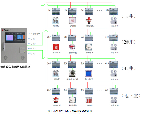
Figure 1 Topology diagram of small fire equipment power monitoring system
3.2 Field monitoring equipment functions and features
AFPM3-2AV three-phase AC dual-supply voltage sensor is used for real-time monitoring and data acquisition of power supply and equipment running status of various fire-fighting equipments in the field. It has over-voltage, under-voltage, phase loss, phase-to-phase alarm and event storage. Function, the alarm can record the time, type and parameter of the alarm. According to the alarm record, the situation can be analyzed to provide a basis for eliminating the fault. In addition, the sensor uses fieldbus communication technology, and the upper computer management software can monitor the operation of the scene in real time. , timely discovery of alarm information. Through the RS485 interface, the standard Modbus protocol can be connected to various standard systems, and has the advantages of high integration, network, high intelligence, and reasonable motion characteristics.
AFPM100/B fire equipment power status monitor adopts centralized and modular design, and is equipped with AFPM3-2AV three-phase AC dual-supply voltage sensor to track the operating information, fault information and position information of the monitored fire equipment power supply. It collects, stores and analyzes, which is convenient for users to manage and monitor. Through the human-computer interaction interface, the working status data of the fire-fighting equipment power supply is displayed together, with many functions such as management, viewing, alarm and printing.
4 system installation design
4.1 System wiring design
The wiring design of the fire protection equipment power monitoring system of the complex building project of this mall should follow the following guidelines:
1. The wiring of the system shall comply with the requirements of GB 50303 "Code for acceptance of construction quality of building electrical installations".
2. Threading in the pipe or in the trunking shall be carried out after the construction plastering and ground works. The water and debris in the pipe or in the trunk should be removed before threading.
3. The system should be wired separately. The lines with different voltage levels and different current categories in the system should not be placed in the same slot or in the same slot of the trunking.
4. The wire is inside the pipe or in the wire slot and there should be no joints or kinks. The connectors of the wires shall be soldered in the junction box or connected by terminals.
5. The joint between the nozzle and the pipe laid in the dusty or wet place should be sealed.
6. After the system wires are laid, the insulation resistance of the wires of each circuit should be measured with a 500V megohmmeter, and the insulation resistance to ground should be not less than 50MΩ.
7. The wires in the same project should be distinguished according to different purposes. The color of the wires for the same purpose should be the same. The positive side of the power cord should be red and the negative should be blue or black.
8. The line distance between AFPM100/B fire equipment power status monitor and AFPM3-2AV sensor should not exceed 500m, and should not be routed in areas with high power and complex environment as much as possible. Communication line between monitor and sensor: ZR-RVSP-2×1.0mm2, power cord specification: ZR-RVS-2×1.5mm2, the above specifications are the minimum requirements. The metal pipe should be used for the line threading pipe.
4.2 Monitor installation design
"General Technical Requirements for Fire Control Room" states: "Fire equipment installed in fire control room shall include fire alarm controller, fire linkage controller, fire control room graphic display device, fire telephone switchboard, fire emergency broadcast control device, fire emergency Lighting and evacuation indication system control devices, fire power monitors and other equipment, or a combination of equipment with corresponding functions." That is, the national standard clearly specifies that the fire equipment power status monitor should be installed in the fire control room. If there is no fire control room, it should be installed in a place where someone is on duty.
The fire equipment power status monitor of the complex building project of this mall is installed in the duty room of the substation. The installation of the monitor should follow the following guidelines:
1. When the monitor is installed on the wall, the height of the bottom edge of the ground (floor) should be 1.3m~1.5m, the distance from the side of the door axis should not be less than 0.5m, and the front operating distance should not be less than 1.2m.
2. When installing on the ground, the bottom edge should be 0.1m~0.2m above the ground (floor).
3. The monitor should be installed securely and must not be tilted. When installing on a lightweight wall, reinforcement should be taken.
4. The total number of devices connected to each bus loop of the monitor should not be too much. It should be left with a margin of not less than 10% of the rated capacity of the circuit, which is convenient for future system expansion.
5. The AC power supply of the monitor should use the fire power supply.
According to the site situation, the fire equipment power status monitor of this project is installed on the wall, and the bottom edge is 1.4m from the ground.
4.3 Sensor installation design
The AFPM3-2AV three-phase AC dual-supply voltage sensor of the mall complex is installed between the output of the circuit breaker or the isolating switch and the input of the dual power switching device. The main power voltage signal is connected to 1, 2, 3, 4 Four terminals, the standby power supply voltage signal is connected to the four terminals 5, 6, 7, and 8. The dual voltage monitoring of the fire hydrant pump distribution box located in the basement area is taken as an example. The installation position of the sensor AFPM3-2AV is shown in Figure 2. The physical installation location diagram is shown in Figure 3, and the voltage signal wiring diagram is shown in Figure 4.
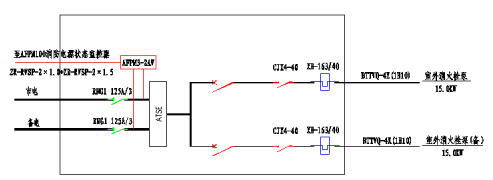
Figure 2 Schematic diagram of AFPM3-2AV installation position
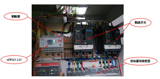
Figure 3 AFPM3-2AV physical installation location map
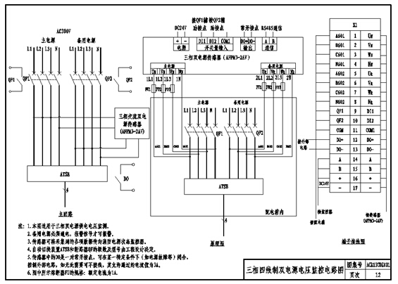
Figure 4 AFPM3-2AV voltage signal wiring diagram
The following guidelines should be followed for the installation of the sensor:
1. Do not install the sensor without cutting off the power.
2. The sensor should be independently supported or fixed, installed firmly, and measures such as moisture and corrosion should be taken.
3. When there is no separate installation condition, the sensor can be installed in the distribution box, but it can not affect the main circuit of the power supply. Should try to maintain a certain distance, and there are obvious signs.
4. The installation of the sensor should not damage the integrity of the monitored line and should not increase the line contact.
5. When the AFPM3-2AV sensor is installed and designed, when the voltage signal is collected, it is necessary to connect the fuses with the rated current of 1A in the phase line, and a total of six fuses are required.
6. The power supply of the AFPM3-2AV sensor cannot be obtained from other places. It must be provided by the fire equipment power status monitor. The power supply voltage is DC24V.
5 system on-site debugging
The system on-site debugging process is as follows:
1. The monitoring system is connected to the power supply. The connection between the host and the sensor is completed. After that, check whether the various connection specifications meet the requirements, and whether the connection is short-circuited or loose.
2. After the construction party has completed the grounding insulation resistance test and determined that the insulation resistance meets the construction requirements, use a multimeter to measure, the insulation resistance of the access line to the earth should be no less than 50MΩ.
3. First power on the sensor, wait for it to stabilize, after the alarm signal acquisition, set the sensor's communication address code, voltage alarm value, etc., and test the various functions of the sensor.
4. Turn on the main power of the monitoring system, use a multimeter to measure whether the voltage on each line is normal, and then configure the system parameters of the monitoring host (including the communication port, the communication address code of the sensor, etc.). Check if the communication is connected. If the communication cannot be connected, check the communication address code and communication line until normal communication. Test the basic functions of the monitoring system, alarms, control output and other functions.
5. All debugging is completed, trial run for 3 days. After the system is accepted, it can be put into normal operation.
The fire protection equipment power monitoring screen of the mall complex building project is shown in Figure 5.
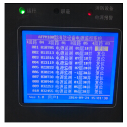
Figure 5 Fire equipment power monitoring screen
6 Conclusion
This paper introduces the design and application of the power supply monitoring system of a shopping mall fire equipment from three aspects: system networking design, system installation design and system on-site debugging. Fire equipment power monitoring system is still a new thing, the relevant standards and application mechanisms are not sound enough. With the specific application of the related products of the system in practical situations, relevant problems and deficiencies will be dealt with and solved as expected. Fire equipment power monitoring system as an early warning system, with the actual use of the site, the operational reliability of the fire equipment in the mall will be well guaranteed, thus protecting the normal operation of the mall and the safety of people's lives and property [4] .
Article source: "Intelligent Building Electrical Technology", No. 1, 2015
references
[1] Shenyang Fire Research Institute of the Ministry of Public Security, Liaoning Provincial Public Security Fire Brigade, Zhejiang Public Security Fire Brigade, etc. GB 25506-2010 Fire Control Room General Technical Requirements [S]. Beijing: China Standard Press, 2011.
[2] Shenyang Fire Research Institute of the Ministry of Public Security, Beijing Hengye Century Technology Co., Ltd., Beijing Yuanjie Electronics Co., Ltd. GB 28184-2011 Fire Equipment Power Monitoring System [S]. Beijing: China Standard Press, 2012.
[3] Zhou Zhong. Product selection and solution for smart grid customer power monitoring and power management system [M]. Beijing: Mechanical Industry Press, 2011.
[4] Shenyang Fire Research Institute of the Ministry of Public Security. GB 50116-2013 Fire Alarm System Design Specification [S]. Beijing: China Planning Press, 2014.
Technical support: Yang Junjun, contact phone, mobile phone, QQ
Http://news.chinawj.com.cn Editor: (Hardware Business Network Information Center) http://news.chinawj.com.cn
Specification:
| Name | Brass bath spout chrome plated round design water saving spout |
| Material | Brass, Chrome |
| Function | Cold and hot water mixing |
| Usage | Bathroom equipment |
| Guarantee | 5 years |
| MOQ | 50 pieces |
|
Package |
Inner packing: bubble package,cloth bag, white or color craft carton Outer packing: kraft carton Can be designed by customer |
|
Plating thickness |
The chromium layer is 0.25-0.45μm, nickel layer is 7.5-9.5 μm |
|
Shipping terms |
FOB Jiangmen or EX-Work |
|
Delivery time |
15-30 days after receiving deposit. |
| Payment | T/T |
Round Brass Spout,Brass Tub Spout,Round Brass Long Spout,Round Solid Brass Spout
KaiPing HuiPu Shower Metalwork Industrial CO,LTD , https://www.hp-shower.com