Abstract: The propulsion system is one of the key systems of the shield machine. This paper describes the principle of the shield hydraulic propulsion hydraulic system. The system was simulated using the AMESim simulation tool. The simulation results show that the conventional pressure control will cause the flow to fluctuate drastically, and the conventional flow control will cause the pressure fluctuation. The pressure flow combined control mode can perform the pressure closed-loop control or the flow closed-loop control, thus reducing the fluctuation of pressure and flow. Achieve real-time control of propulsion pressure and propulsion speed.
Keywords: shield machine, propulsion hydraulic system, pressure flow combined control; AMESim simulation
1 Introduction
The shield tunneling machine is a complex electromechanical system used for excavation of underground tunnel engineering. It has the functions of opening and controlling cutting soil, conveying soil, assembling tunnel lining, measuring guiding and correcting deviation. Shield tunneling machines have been widely used in subway, railway, highway, municipal, and hydropower tunnel projects. The utility model has the advantages of high excavation speed, high quality, small labor intensity, high safety, small surface subsidence and environmental impact, and has obvious advantages compared with the traditional drilling and blasting tunnel construction, and has good comprehensive benefits.
The propulsion system undertakes the jacking task of the entire shield machine, and requires the turning, curve travel, attitude control, rectification and synchronous movement of the shield tunneling machine to make the shield tunneling machine advance along the previously set route. One of the key systems of the machine.
Considering that the shield tunneling machine has the characteristics of high power, variable load and power long-distance transmission and control, its propulsion system uses hydraulic system to realize power transmission, distribution and control.
In this paper, the AMESim simulation tool is used to analyze the relevant conditions of the hydraulic system of the shield propulsion system. The simulation results are of great significance to the design of the actual system.
2 Introduction to the principle of propulsion hydraulic system
The schematic diagram of the hydraulic system of the shield machine is shown in Figure 1. The proportional relief valve 3 adjusts the pressure of the hydraulic cylinder to achieve the pressure control; the proportional speed regulating valve 14 regulates the flow entering the system to achieve the speed control; the three-position four-way solenoid valve 12 realizes the propulsion, retreat and stop states of the propulsion cylinder; Valve 1 provides a fast flow path for rapid movement of the propulsion cylinder, reducing the pressure loss of hydraulic oil entering the cylinder. The insert 13 can realize a quick circulation passage for the rapid retraction of the propulsion cylinder and reduce the hydraulic oil return stroke resistance. The relief valve 10 can buffer the system. When the hydraulic cylinder advances, there will be an instantaneous overload at the inlet, so that the relief valve will immediately open to form a short circuit, so that the inlet and return lines are self-circulating, and the oil is overloaded. The buffer is obtained; the 2/2-way valve 7 is energized to unload and repair the hydraulic cylinder in the fault, reducing the pressure shock during unloading. The orifice is used to adjust the opening speed of the cartridge valve, change the static and dynamic characteristics of the cartridge valve and reduce the hydraulic shock, and prevent the pressure shock generated when the 2/2-way valve 7 is unloaded. The diameter of the orifice is generally in the range of 0.8 to 2.5 mm.

3 propulsion hydraulic system simulation analysis
3.1 Simulation model
When the shield is propelled, the cartridge valve 1 of the system is closed, the three-position four-way valve 12 is placed in the right position, and the hydraulic oil flows into the cylinder without the rod through the proportional speed regulating valve 14 and the three-position four-way valve 12, and has a rod. The chamber hydraulic oil flows back to the tank through the three-position four-way valve 12 and the proportional relief valve 1. When the shield tunneling, the cartridge valve 1 is opened, the three-position four-way valve 12 is placed in the left position, and the hydraulic oil flows into the hydraulic cylinder to have a rod cavity, so that the cylinder is retracted. The proportional pressure valve and proportional speed control valve are used to set the system pressure and adjust the speed of the system. In order to simplify the analysis and facilitate the simulation, the cartridge valve 1, the cartridge valve 13 and the three-position four-way valve 12 can be omitted, and a simplified schematic diagram is shown in Fig. 2.

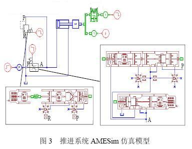
A simplified simulation model of the system using AMESim is shown in Figure 3. The hydraulic input takes the constant pressure input model PRSEC, the hydraulic cylinder selection system model HJ010 as the actuator, and the piping selection system HL000 [5]. Since the AMESim software itself does not have a proportional speed control model valve and a proportional pressure valve model, the HCD (Hydraulic Component Design Module) is used to establish its HCD model as shown in Figure 3.
When the pressure reached 8.5Mpa during simulation, the load speed increased from 0 to 0.001mm/s, and the load force was set to constant: 12361N.
3.1.1 Propulsion pressure open loop control simulation
The flow valve flow rate is set to 11.4L/min, the pressure valve is 10.5Mpa, and the load speed is increased from 0 to 0.001m/s when the hydraulic cylinder pressure reaches 8.5Mpa. The pressure valve is adjusted to 10.5 MPa at 100 s and to 9.0 MPa at 200 s. Figure 4 is a pressure diagram and flow rate diagram of the hydraulic cylinder when the pressure is adjusted. The 1# curve is the hydraulic cylinder pressure change curve, and the 2# curve is the hydraulic cylinder flow rate change curve.
Figure 4 Hydraulic cylinder pressure and flow curve when adjusting pressure
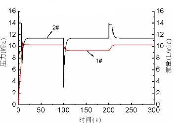
When the pressure is raised, the hydraulic cylinder speed rises with a large fluctuation until the pressure reaches the new pressure value set by the pressure regulating valve. When the pressure is lowered, the hydraulic cylinder speed drops greatly and fluctuates until the pressure reaches the new pressure value set by the pressure regulating valve. Therefore, the hydraulic cylinder should be slowly adjusted to prevent the cylinder speed from changing too much.
Next page
Okouman Plywood,Bed Slat Plywood,Commercial Plywood
Linyi Chanta Plywood Co., Ltd. , http://www.lyplywood.com